Eric Chong
Lab 16: Angular acceleration
Lab Partners: Nina Song and Joel Cook
Purpose: Observe the effects of changing the hanging mass, the radius at which the hanging mass exerts torque, and the rotating mass on the angular acceleration.
Theory/Introduction: The angular acceleration of a disk is affected by the radius of the disk, the rotating mass, and the intensity of the torque exerted at a certain radius. We want to experiment with how each of these factors affect the angular acceleration. We can test the effect of changing the intensity of the force exerted at a certain radius by attaching a string perpendicular to the disk's radius and changing the hanging mass's mass in order to increase or decrease the torque exerted on the disk. We can test the effect of changing the radius by changing the size of the pulley that is made of the same material. We can also test the effect of changing rotating mass itself by changing the material of the disk with an aluminum disk and a steel disk; this change will affect the inertia. By doing this experiment, we can determine how angular acceleration is affected when these factors are incorporated, and ultimately find through calculations how this all comes together. We can also determine certain relationships at the start by looking at the equation, torque = I*alpha, where I is the moment of inertia, and alpha is the angular acceleration. This relationship will be discussed later in the lab.
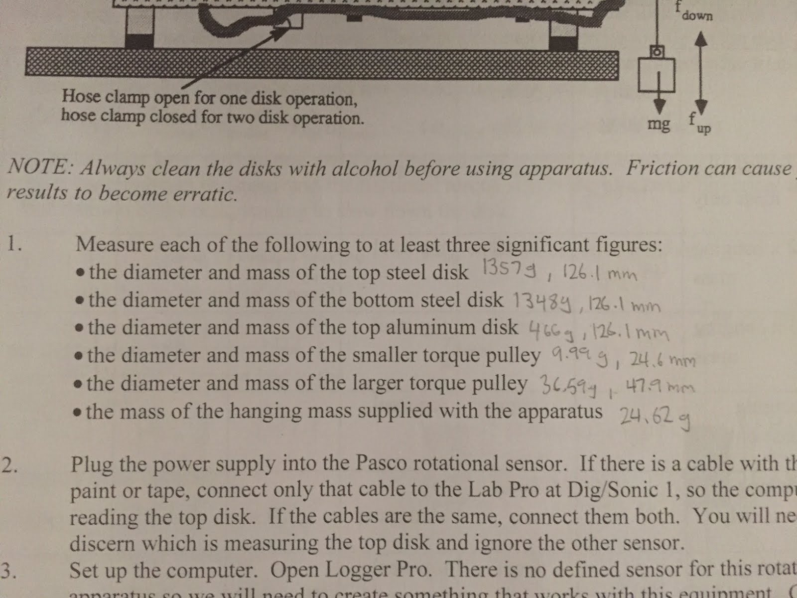
Procedure: Part 1) For this Part of the experiment, we just want to see how the factors mentioned in the introduction affect the angular acceleration of a rotating mass. We start by setting up the apparatus like so:

The hanging mass is connected to a string, which is connected to the rotating mass. An air is used to reduce friction. The apparatus is also connected to LoggerPro in a laptop, so we can measure the angular velocity of the rotating mass, as we observe the factors affecting the angular acceleration. We first observed the effects of the change in the mass of the hanging mass on the angular acceleration, and then the effects of changing the radius, and finally the effects of changing the rotating mass. For the hands-on measurements, here is the data:

Here is what we got on LoggerPro when we changed the hanging mass by doubling and tripling it, the radius of the pulley by doubling its size, and the disk itself by changing it from "top steel" to "top aluminum" and "top steel + bottom steel," in that order:
Here is what we got on LoggerPro when we changed the hanging mass by doubling and tripling it, the radius of the pulley by doubling its size, and the disk itself by changing it from "top steel" to "top aluminum" and "top steel + bottom steel," in that order:


We can look at the angular acceleration by looking at the slopes of the velocity vs. time graphs while the hanging mass was going up and down. Upon observation, the angular acceleration seems to be changing while it is going up and down. We hypothesize that the reason the angular accelerations are different while going up and down is that there is a sort of frictional torque affecting the angular acceleration. To take this into account, we evaluated the angular acceleration by taking the average of the values while the hanging mass is going up and down. Here is a data table of all of the changes we made to the apparatus and its corresponding angular acceleration values:

It seems that by doubling the hanging mass, we also doubled the angular acceleration, and when we tripled the mass of the hanging mass, we tripled the angular acceleration. Furthermore, when we doubled the radius of the torque pulley, we also doubled the angular acceleration. We can also determine through the analysis of the torque = I*alpha equation that it is likely that changing the inertia will have an inverse effect on the angular acceleration. We will explore this idea more in part 2, when we start calculating the moments of inertia.
Part 2) For this part of the lab, we need to determine experimental values for the moments of inertia of the disks, using the data we took from part 1. To do this, professor gave us an equation he derived for us:

(note: m is the mass of the hanging mass, r is the radius of the pulley)
We can use this equation and plug in the corresponding values in order to determine the moments of inertia of the disks. We can use the values we previously measured in the hands-on measurements part of the lab, and calculate the moments of inertia of each disk or disk combinations. Here is a sample calculation of expt. 1:

Here is a data table of all of the moments of inertia values we calculated:

Based on the data, it is expected that all of the first three inertias be the same, because the material and the size of the disk are the same. However, once we changed the material and size of the disk, we either increase or decrease the inertia. Based on the data and the comparison to the angular accelerations measured in part 1, it can be seen that an increase in inertia has an inverse on the angular acceleration, meaning that increasing inertia decreases the angular acceleration.
Conclusion: Through this experiment, we determined that the angular acceleration increases with an increasing torque, an increasing radius, and a decreasing inertia. This makes sense because a stronger torque means a stronger pull on the radius, and a larger radius means that it makes it easier for the point on the radius to be pulled, and a decreasing inertia means that certain objects are easier to be moved. In this lab, however, we encountered an uncertainty in the frictional torque. We countered this by taking the average of the angular accelerations going up and going down. But, this is only a general assumption that taking the average could solve the problem. It will not help us get an exact value. There is also uncertainty in the pulley, as it is not an ideal pulley. And finally, there is also uncertainty in our hands-on measurements when we measured the radius and the masses. Overall, the lab is able to showcase the effects of changing the radii, the torque, and the inertia. And this agrees with the general formula of torque = inertia*alpha.
No comments:
Post a Comment